Thank you gents!
As far as the design process goes, it’s really simple and complicated at the same time.
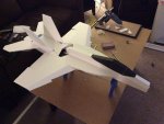
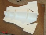
The overall design work is aircraft dependent. The F-18 prop and slot was fairly simple. The FH-1 prototype was pretty complicated. The new FH-1 V2 is way too complicated for what it is, but I am using all of this for testing and experimentation. The FH-1 is a special case where the engines are mounted in the wing root which causes all kinds of technical issues. I got around that with the prototype by mounting the engines aft of the wing spar and cutting holes in the bottom of the wing to let them breath better. Version 2 I figured out a way to mount the EDF’s in the wing spar but it complicated the build quite a bit. The wing spar / engine mount looks strong enough, but I will not really know if it will hold up until the maiden flight.
Exciting stuff!
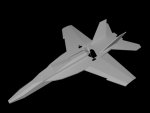
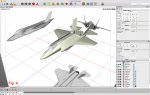
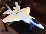
Workflow starts with picking a subject, scale and electronics. In this case I wanted a Prop and Slot F-35. With this particular build the scale was set by the motor and prop I had available at the time. Most of my new builds are set to a scale of 1:12 or 1:10 and I buy the electronics for that size.
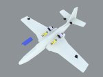
Next is a 3 view of the aircraft and then a low poly mock up. I model all of the electronics I plan to use as well. This adds quite a bit of time to the design process for the first few models, but once drawn you can use those for future designs where applicable.
See Fig A.
I use Dollar Tree foamboard for these builds which I can buy locally dirt cheap, but there are plenty of materials out there to use. Foamboard as a thickness of 0.1875” so I create a box 1x0.1875x1 to use for building each face of the structure.
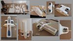
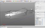
The fun part begins with converting the low poly mock up to the actual design. There is no trick to this, you just have to know how the foam behaves. It’s just like paper. You can bend it, but only on one axis at a time. Rounded bends can be achieved by removing the paper from one side but it loses some strength and it’s a lot more work. It’s easier to score one side and bend along the crease. Once you wrap your head around that you can wrap your mock up with foam faces.
See Fig B.
The UV unwrapper in Cheetah like most other programs does not care about scale or face geometry so you are going to have to unwrap this thing yourself. In order for this to work you have to model each face as it’s own object. This is a very time intensive process that you can not get around unfortunately. When you are placing the faces together, picture each 3D face as a piece of foam. Treat the outside top and bottom faces as a paper skin and the ring faces that make it’s depth as foam. It’s important to move and rotate the “foam face” as an object to get it into location. On folds, treat the outside paper face as the skin, the interior face will compress when bent. (The outside face will make your template, the inside fades will over lap and look messy but are not important) Once in place you can move each vertex around any way you like, but only using “object” coordinates and in two dimensions . Do not move the points on the Y axis at any time. Using these rules, place and tweak each piece until you get the desired result.
See Fig C.
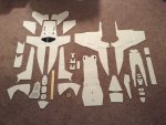
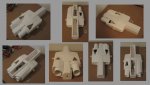
Once you have all of your 3d faces placed and aligned, you now have to pull them all back apart again. At this point you never want to touch a vertex. Each face will be reoriented and laid flat next to its neighbor matching the faces by “object” rotation and position. Each stitched back together laying flat.
See Fig D.
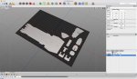
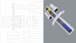
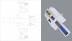
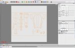
Once you have manually unwrapped your foam skin you now have you basic template for your foam. To keep everything scale you will need to create a face to an exact known dimension. Im my case my foam board is 20”x30” I create a face 20 x 30 in Cheetah and place all of my templates in this square and combine them. With my new 20 x 30 template I take it into the UV mapper and do a Cubic mapping of the template with a scale set to 1” larger than the template which is 31 x 1 x 31. Once I write the UV’s I export to PDF.
See Fig E.
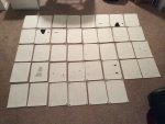
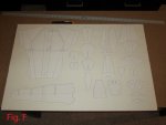
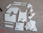
And finally, import the PDF in photoshop with the dimensions of 31 x 31 @ 300 DPI. Next using the magic wand tool I do an area selection inside of the square template. @ 300 DPI the UV lines are about 4 pixels wide so I expand my selection by 2 pixels. Once expanded, crop the image by selection and you are good to go. You now have a 100% accurate template to cut out your foamboard.
This long post is just scratching the surface. If you are really interested in building your own RC aircraft, I would suggest checking out the “FliteTest” YouTube channel. Those guys do all sorts of crazy things with RC and are foamboard aircraft pioneers. I have done some cool stuff, but there are plenty of more talented people than I out there that do this sort of thing. I am just the only insane one manually unwrapping models in Cheetah 3D which allows me to get more intricate than most, but still using cheap and sometimes easy foamboard builds.