Please critique
Hello everyone,
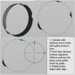
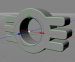
I am very much a noob but I am finding C3D extremely easy to learn and use. I have set myself a task to model a motorcycle engine. I am at the point where I am doing the fins with cutouts. I did the cutout by using the scalpel tool and then deleting ploys on the modelled upper face of the fin. Then mirror and bridge to give both upper and lower. Then inner extrude the edge of the cut and manually clean up around the cut. The manual clean up is quite labour intensive and I have a number of fins to do! Any comments or criticisms would be welcomed - especially any tips.
Thank you and regards,
Paul
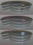
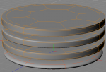
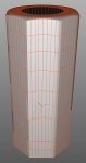
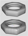
Hello everyone,
I am very much a noob but I am finding C3D extremely easy to learn and use. I have set myself a task to model a motorcycle engine. I am at the point where I am doing the fins with cutouts. I did the cutout by using the scalpel tool and then deleting ploys on the modelled upper face of the fin. Then mirror and bridge to give both upper and lower. Then inner extrude the edge of the cut and manually clean up around the cut. The manual clean up is quite labour intensive and I have a number of fins to do! Any comments or criticisms would be welcomed - especially any tips.
Thank you and regards,
Paul
Last edited:
")