
Hi everyone,
I keep having issues with the UV mapping in Cheetah. Most of the time it does as expected but I'm not going to lie, it often times feels like a black box to me where I just kinda hope it works.
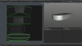
I have a simple model here and made (what I felt) were some reasonable cuts to UV map this object. The problem is that it seems to warp one side of the object more than the other and also doesn't scale things appropriately as you can see.

Does anybody have any idea why this could be happening?
I'm also wondering what the difference is in the Unwrap with LSCM and Unwrap with ABF options?
Thanks and looking forward to any and all replies!
I keep having issues with the UV mapping in Cheetah. Most of the time it does as expected but I'm not going to lie, it often times feels like a black box to me where I just kinda hope it works.
I have a simple model here and made (what I felt) were some reasonable cuts to UV map this object. The problem is that it seems to warp one side of the object more than the other and also doesn't scale things appropriately as you can see.
Does anybody have any idea why this could be happening?
I'm also wondering what the difference is in the Unwrap with LSCM and Unwrap with ABF options?
Thanks and looking forward to any and all replies!

 many thanks