Frontal Projection Squished?

Hi!

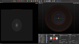
I have a round object that a orthogonal camera is looking at with a square aspect ratio (1080x1080).

When I use the mapper's "frontal" projection, it should be looking through the camera, right? The issue is that the resulting UVs are not round but squished and I can't figure out the aspect ratio to put into "UV Transformation" to get a proper camera projection.

I attached a picture of the issue (the UVs on the left side are the result of "frontal" projection.).
 

Attachments

  • bug.jpg
    bug.jpg
    471.6 KB · Views: 131
This happens with front projection regardless of the Camera setting.
You should use Flat projection here.

Look at the orange line at the top of the UV window, looks like it's applying edge on.
 
When I use the mapper's "frontal" projection, it should be looking through the camera, right?
Hello,

Camera view and “frontal” projection are not automatically one and the same. “Frontal” is the front of the object as it is oriented in 3D space. It has nothing to do with a camera unless that camera and the front of the object are in agreement.

Making a UV of a round (or even slightly curved) three dimensional object is _always_ going to involve distortion. IF you haven’t, take a look at the UV of a parametric sphere for what is the default distortion to get a UV from a sphere… it is not “round” at all.

ZooHead suggests a Flat projection. Depending on what you are working on, that may or may not be the best choice. It is certainly worth a shot. And unlike “frontal”, “Flat” allows you to easily determine the orientation of the flat plane to your object.

The resulting look of an spherical 3D object, with an image applied to it that was made using an UV map to the sphere from the “front”, might look the way one expects from the “front” but it will look way distorted from the “side”. And that might be a desired result.

As for the UV mapping you got being a bug… nope. Believe it or not, what you got is the what you asked to have happen.

When making UV maps, we typically need to figure out how to get the best distortion result we want that is easiest for us to use to do what we want to do next.

Hope this helps.

Cheers,
gsb
 
Unfortunately I can't help you with the settings because I've never used the UV Mapper - I've only worked with Unwrap. But the oval shape might actually distort your texture. I tried it with the reptile texture (set to UV 1):

uv_oval.jpg


uv_round.jpg


In the first example the texture is distorted. In the second example I just selected everything in the UV window and scaled it to the width until it was round. This is certainly not the most professional solution, but normally I just distort everything in my UVs until it fits. It might be a botch job, but it's quick and easy. ;)
(But as I said, since I have never used the mapper before, I don't know if this can lead to other problems...)
 
I know I can scale it, but yes, then it isn't perfect.

What I'm doing is that I'm rendering something high poly and then I want to project it onto a flat disc pixel-perfectly. Therefore, I need the projection to be exactly the same as when I rendered it earlier and I know it can be perfect because I used a orthographic camera and my projection surface is flat.

My object isn't spherical, but flat, so that should work.

When I use "flat", the center is at 0,1 UV coordinates and the result is way too big.

Basically what I'm looking for is a camera projection where the UVs will look like the wireframe of my mesh in the camera preview but I guess I can do some math to turn "flat" into a centered one with the correct scale according to the resolution. (one unit in my scene is 1 pixel).

Looks like I get what I want if I use camera width/2 and height/2 in "offset" and 1/camera height and width for scale x and y :)

The only problem now is that it looks like it's not possible to give different morph targets of the same mesh different UVs projections?

Edit: attached my scene for reference
 

Attachments

  • Morph.zip
    78.5 KB · Views: 101
Last edited:
There are so many things I don´t understand with your file.
1. Why is it a that large scale?
2. Why the Morph-tag instead of the transform-modifier
3. Why is it rotated rotated P=90°?
4. Why not using a Disc object or cover of a cylinder which will offer perfect UVs by default same with a circle spline attached to a Polyplane Creator where you can animate the size of the circle and its fidelity?
just to start with.
 
Last edited:
  • Like
Reactions: gsb
it's at a large scale because it's for a pixel-perfect projection where 1 unit corresponds to one pixel on the screen.
It's rotated 90° because I import that into Unity where the camera typically looks at things from the front.
The Morph tag helps me interpolate between different shapes. That's also why I can't use a cylinder, because I need to customize the position of the edges to be roughly where significant edges are in the rendered textures The shape isn't just scaling but the edge loops move so I can blend between the rendered textures while maintaining the width of the edges.
(I attached a video of what happens. in the end, there's a shape morph going on at the same time as a blend between textures)
 

Attachments

  • asd.mp4.zip
    486.6 KB · Views: 101
Last edited:
Hello,

Accepting that you have a firm idea of what you are trying to do, but are not getting the results you think you should be, try changing a few things a bit. A key question in Frank’s post, was why you rotated your model 90°. Your answer was basically so that it faces front. Get it to face front without a transformation.

You need to get rid of that transformation before you create your morphs otherwise unexpected things might DO happen.

E.G.

Using your example model, if one tries burning the transform 90° rotation, so that the model isn’t transformed (rotated) and yet is still properly facing the front view, and attempts to performs that burn with the morph tag active, then the model vanishes.

But burn the transform with the morph deactivated and then things behave the way they are expected.

“Expected" includes creating UVs using the UV Mapper tool with the flat projection (as Zoo suggested you do) with the result of a circular, not a non-round oval, UV.

And when one reactivates your morph, the model morphs in ways that you clearly did not desire. One can easily see a flat UV Mapper projection of that shape resulting in a non-circular oval

I can’t speak to whether or not your morph-tag and UVs will do what you ultimately expect, but if you create a new morph tag with the model properly aligned in C3D, without transformation, you’ll be a step closer to what you expect as far as getting circular UVs from a circular model.

hope this helps

cheers,
gsb
 
I got the results I wanted by manually putting in the projection size based the camera.
Looks like I get what I want if I use camera width/2 and height/2 in "offset" and 1/camera height and width for scale x and y :)
The separate UVs I ended up doing in Maya now.
 
Hello,

Happy that you got the results you wanted. Yes, you certainly did report that you got what you wanted by calculating a scale factor. Good problem solving to be sure.

But it seemed like it might be valuable to know _why_ you got the UV results you did so you (and others who stumble upon the same trouble) can avoid the problem in the future without having to find a creative “fix” to compensate for the mistake.

It wasn’t a bug.

So, for this is for others who may want to avoid the trouble the OP had… Before making UVs, make sure that the object isn't transformed (scaled and/or rotated). When creating the object, if scaling and rotating and scaling were necessary to get a proper size or face orientation, remember to use the Coordinate System Tool to burn transformation and/or scale before using the UV Mapper.

At least this has been my experience.

Cheers,
gsb
 
Back
Top