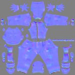
Cheetah 3D Node Math Exploration

I’ve been asked to add some comments to the forum about how I approach designing Node-based textures. To do that (and keep it comprehensible), I’ve got to explain a few things about what I know, what I don’t know, and many things I’ve guessed.

I’ll start with the basics and work my way up, so please forgive me when I run out fo fuel somewhere in the middle, because I certainly don’t know it all. Once I get technical, I may very well be wrong. This is almost all based upon observation, not formal education.

I STRONGLY recommend reading the thread “Quick And Dirty Introductions to Node-based Shaders” by PodPerson. Lots of good info and brief definitions of Cheetah3D’s Nodes.

In this thread, intend to talk more about understanding the numbers than digging into any particular Node. Feel free to jump in.


To work with Nodes it’s important to understand that for values, they use either Numeric values or Vector values. Numeric values are made of sets of three numbers - very handy for a number of reasons in a 3D graphics setting.
  • Vectors can describe a location - the X,Y,Z coordinates of any point.
  • They also are used to describe colors - in particular, the Red, Blue and Green components of a screen color.
Most nodes will generate output as vectors ( X, Y, and Z values, referred to as “Vec” or “Color” ) and/or as Numeric, floating point values ( referred to as "Val". The interfaces may not change, but usually, a single value is stored in the X component’s field. The Y and Z fields may not affect the output if the process expects a Number instead of a Vector input. ).

To convert between these formats, there are a pair of Math Nodes, Vec2Float and Float2Vec. I’ll talk about them in the first example.
 
Dynamic Color Creation:

There are several easier ways to build a color, but this will get you into the habit of thinking of colors as a set of numbers instead of as a single value.

First, create a Default Material, select it, and switch to the Nodes Editor by clicking the Nodes Tab located towards in the upper left of the main screen.

(Whenever I do this, nowadays, I almost always replace the default Materials Shader with the newer PBR Shader. With a very few exceptions, it seems to give me greater control of the final texture. Just command click on the Node editor screen and select the PBR Shader from the dropdown’s Shaders submenu group.)

Then, command click in the screen to display the Node Editor’s dropdown menu. Under the Add Node item, go to the Constants submenu and create a Number Node. Do this FOUR times. These will be used to create Red, Blue and Green values you can edit manually, as well as an Alpha value, to handle transparency, something even the dedicated Color Node doesn’t do.

On each Node, the values listed on the left side are input values, the ones on the right are output values. By clicking on an output connector (the dot graphic) you’ll toggle a representation of the how the input values are interpreted on a 3D sphere. A Numeric ("Val") preview is grayscale, the others may or may not be in color.

Now, use the command click dropdown menu again to create your first Math Node. Choose Float2Vec, a Node which combines three Numeric values to create a single Vector value. (There is a fourth input - "W", representing transparency - is used for creating colors.)

Drag a connector line from the first Number node’s "Val" output to the Float2Vec Node’s "X" input. Connect the second Number’s output to input "Y", the third Node to input "Z", and the fourth to "W".

Screen colors that Cheetah’s generic color picker produces are generally Numeric floating point values between 0 and 1. For example, populate the “Red” ("X") Node’s Number value with 0.8 and the “Blue” ("Z") Node’s value with 0.3. Leave the “Green” ("Y") Node’s value at 0 or blank, and add a 1.0 value to the "Alpha" ("W") Number.

Each of the Number Nodes’ sphere graphics will become some shade of gray, while the Float2Vec’s sphere will take on a reddish tone. Now connect the Float2Vec output to the PBR Shader's "Base Color" input.

Color Node Example.jpg


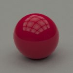
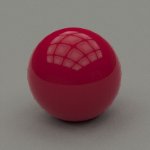
Play With the first three Number values to see how the color changes. If you want to create a traditional Color Node, go back to the Dropdown menu, under the Constants submenu. Notice that a Color Node does NOT have input values. I matched the standard Node to this constructed color by generating RGB values to select in the RGB color picker by multiplying the Number Nodes' values by 256. (204, 0, 77 and 100% for the Alpha Channel)

Calculated Color.jpg The Constructed Color Node
Basic Color.jpg The Matching Standard Color Node
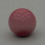
Transparent Color.jpg The Constructed Color Node with Transparency

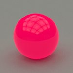
Back in the PBR Shader, I connected the output of the Matching Standard Color Node to the PBR Shader's "Emissive" input.

Emissive Color.jpg The Constructed Color with a matching Emissive value.

Why did I do this? Because if you are Manually constructing colors WITHOUT the standard Color Picker, you can "supercharge" any of the values. By this I mean that you aren't limited to floating point values between 0 and 1. For instance, look what happens when I changed the "Alpha" value to 10!

Supercharged Color.jpg
The Constructed Color with an Alpha "W" value of 10.

It's a very different appearance than the straight Emissive value. It's also different than doubling the Component Number values to (1.6, 0, 0.6 ) or increasing the Intensity value of the Matching Standard Color Node.

You just can't do this by sticking to the color picker. By breaking the color values up into Numeric values that you can play with, you'll start to learn how to think of the colors you need as numbers instead of just "colors", one step closer to adding Texture Nodes to the mix, making color a more integral part of your textures.
 
Last edited:
Using Coordinate Space: Part I

This is another experiment to lead you into thinking of color numerically.

First, Create a basic cube object. Its default measurements are 1 x 1 x 1, and it should be centered upon point ( 0, 0, 0 ).

Now, we’ll create a constructed color - but instead of Number Nodes, we’ll use Nodes to grab a reference point in space: the center of the cube. Command click to show the Node editor’s dropdown menu and select State from the Other submenu.

The State Node’s output presents a set of characteristic values stored in the object to which the Material has been applied. The first Output listed is the Object’s Position in Units. Go ahead and click the Position Output to display its sphere graphic.

At first glance, this graphic (a multi-colored sphere) may be confusing, but it’s actually pretty simple: the colors are defined by the XYZ coordinates of the surface of the sphere. Combining each of those colors creates what you see.

Create a Vec2Float Node, and connect the Position output of the State Node to its Vec input. Now click the “X” output. The sphere display is a view of the objects front. So, X coordinates on the image change from low values on the left (0) to higher values on the right (1). Since Since Cheetah interprets XYZ vectors as RGB colors, the X values in a combined color vector are displayed as Red. (Y is displayed as Green, and Z is displayed as Blue). The output connector allows you to see (and use) a single channel.

Connect the X output to the Materials Shader’s “Diffuse” input. The Shader’s graphic should become identical to its input.
Gradient Basic .jpg

Apply the Material to your cube and render it.

Gradient .jpg

(Continued…)
 
Last edited:
Using Coordinate Space: Part II

My first response was “Shouldn’t the right face be White since only X coordinates are used?” But I was overlooking some simple math.

The coordinates the material grabs from the State node isn’t the XYZ position from the center of the Scene, it’s the XYZ displacement from the center of the Object! Therefore, the left side of the Cube from the front has values less than zero, while the right face of a 1 unit-wide Cube has an x-coordinate of 0.5 units.

(Also, remember that since the values being used to build your color are derived from the Object itself, moving the object around in space won’t change the color.)

Change the Cube’s Width parameter to 2, and you’ll see the White face on the right side.

Gradient Wx2.jpg


However, we don’t want to have to modify the model to get the color we want. So there are several simple Math solutions. Change your Width back to 1.

We know our values range from 0 to .5, while we want them to range from 0 to 1. So the first step seems like it would be “multiply by 2”. We’ll try that.

Add a new Math Node to your material - the Multiply Node from the Math submenu. Connect the X output from Vec2Float to the A input, and click the Val output on the Multiply Node. Your input was a Number, not a Vector, so we’ll keep the flow consistent for the moment. In the Multiply Node’s Properties tab, change the first value in the three B fields to 2. Now, the Node is simply multiplying the X value from the input by the X value in the B vector.

Remember how I mentioned that Number inputs usually ignore Y and Z fields? That happens here as long as your output is also a Number. Change the output to Vec and the display will merge all the values into a Vector, and the preview will make the X channel Red. To keep it neutral, the simple solution is to use the Val output.

Gradient Basic Multiplied.jpg
When you render it, you’ll see that we’re closer, but still wrong.
Gradient x2.jpg

(Continued…)
 
Last edited:
Using Coordinate Space: Part III

We got our white face on the right side, but the Cube is still gradated on the right half, but solid black on the left. Why? The same reason the colors don’t change when we move object: the Node’s XYZ coordinates are derived from the Object’s center, not its left side.

Our ‘simple’ solution was overkill. Instead of just altering the numbers, we need to “move” the object’s center.

Now, we could cheat.

The “center” that the State node uses calculate the XYZ coordinates is actually the object’s Pivot Point, which you can move around under the right conditions. But you can’t burn the Pivot Point of Cheetah3D’s pre-built objects until you convert them to polygon shapes, and we don’t EVER want to modify a model just to get a color correct, anyway.

So, back to the drawing board. We want the gradient to extend from 0 to 1 units, which it already does. It’s just in the wrong place. So we will displace it, using simple addition.

Delete the Multiply Node, and replace it with an Add Node. It works the same way: connect the X output from the Vec2Float Node to the A input of the Add Node, and enter 0.5 into the Add Node’s first B input field.

Gradient Basic Added.jpg


Gradient Shifted.jpg

EUREKA!

Our original range stretched from -0.5 to 0.5, and the shader rendered everything less than 0 as black. By adding 0.5, it now runs from 0 to 1 - precisely what we wanted!

Now, an important side note. If you alter the parameters of a prebuilt object, the material is not altered. But if you stretch or rotate the object, the objects internal math (AND the textures built on that math) ARE transformed along with it.
Gradient Resized.jpg

Altered

Gradient Stretched.jpg

Stretched

You can also alter the object’s Shading Space, by clicking on the material icon next to that object in the Objects tab. (We could have shifted the material on the object this way, too - affecting only this one object - but I wanted to concentrate on the math.)

(Continued…)
 
Last edited:
Using Coordinate Space: Part IV

Remember way back at the beginning, when we first connected the Vec2Float’s X output directly to the Materials Shader’s Diffuse input? Replace the Materials Shader with the PBR Shader and connect the X output to the PBR’s Base Color input.

Gradient PBR .jpg


The Material shader’s Diffuse input has a little intelligence built into it for when you connect a Numeric input instead of a Vector: Any XYZW values that you don’t supply are set from the values ( 0, 0, 0, 1 ), making it easy to drop color changes through the connection. If you drop a single Numeric value into the PBR shader’s Base Color input in the same way, all the other values in the translated Color Vector are set to 0 - including the Alpha channel.

Gradient PBR alpha.jpg


To get the same result as the Materials Shader, a little more work is required - add a Numeric input of 1 to the W input, and combine the two values you are supplying using a Float2Vec Node. Your Float2Vec preview sphere should now display the X value as Red, since the combined value is now a Vector. If you want to change it back to Gray, drag new Output connectors from the X output to the Float2Vec’s Y and Z inputs. Now that you are combining all three inputs using identical values, they all display as neutral colors across the spectrum.

Gradient Final PBR .jpg
 
A Constructed Bump Map

We’ve used Nodes to build a gradient, now let’s use that to mask a second texture. A bump map will demonstrate this very well.

First, we’ll need a model to use it on: a drinking glass.

I built the following Pilsner-style glass from a Cylinder Object. It’s about 7 units tall, with the base and the upper rim using about 1 unit of that height. The sloped exterior is made of a single ring of polygons about 6 tall. Since we want a texture only on those sides, our texture will wind up about 6 units tall. The remainder of the surfaces will use Cheetah3D’s default glass material.

Glass A.jpg

What I planned was a pretty strong texture at the top of the glass which almost faded completely as you follow the sides downward towards the base.

The easiest way to eliminate a texture value is to multiply it by 0, which will change all of its values to 0 no matter what it originally was, so whatever texture I choose, I will want to multiply it by a gradient that goes from 1 to 0. We already know how to make that.

Load a State Node, connect its Position output to a Vec2Float node. Since we want our gradient to run vertically, click to preview the Y output.

If our Texture will wind up 6 units tall and the 0 point will be in the center of that object, our gradient’s value range currently will run from -3.0 to 3.0 units. We want it to start at 0, so we’ll shift it by adding 3 units. Now, we’re running from 0 to 6.0 units. We want out gradient to have values from 0 to 1.0 units over that length, so divide this shifted gradient by 6.

Summary: add/subtract to shift an axis-based gradient along the length of its axis, multiply/divide to increase or decrease the magnitude of its values.

With those 4 Nodes, we now have our black ( 0.0 ) to white ( 1.0 ) gradient which stretches over 6 vertical units. Multiplying another texture by this will mask it by leaving the top edge the same (since it is multiplied it by 1) and gradually reducing its values as you move 6 units lower, until you reach the bottom edge (which is multiplied by 0). Now we need to choose a texture to mask.

I’ve never used the Dots Node since it seems to be applied from the axis directions, making it appear irregular on sloped, angled or curved surfaces. BUT, I was tinkering with it recently and discovered that if you switch its Sample property from 3D to UV1, it appears to change its mapping from cubic to cylindrical, which allows it to wrap nicely around this particular glass model.

By applying this texture (after slightly scaling, and stretching it vertically) to the PBR shader’s Base Color input, I get this:

Glass B.jpg

That appears to have a good set of values from 0 to 1, so I applied it to the PBR Shader's Bump input:

Glass C.jpg

That’s nice and regular. Now it’s time to apply the mask. Add a Multiply Node and connect the output of our gradient (“Val”) to input A and the Val output of the Dots Node to input B. Connecting this to the Bump input of the shader produce this image:

Glass D.jpg


Glass Node.jpg

Now, the bump texture almost disappears by the time it reaches the glass’s base. Note that the previews in the Node editor don't do a great job of representing what's going on. I suspect that is because the previews are of a 1 Unit sphere, so our 6 Unit tall texture doesn't change much over that smaller span. Trust the math, and preview in your scene.

Add the Glass Material to your file’s Material list. Then select the default material listed beside the glass’s item in the Objects tab’s Materials menu (in the Properties Tab) and change it to the newly added Glass Material.

Modify your custom Material by replacing the PBR Shader with a Dialectric Shader (the same as is used in the Glass Material). Connect your Multiply Node’s Val output to the Dialectric Shader’s bumpmap input. This should completely remove your Default material and replace it with glass.

Glass E.jpg


Your mask is nothing more than a linear gradient, from black to white. You could also use the Sine Node to create a non-linear gradient. Copy the glass, use what you’ve learned here and give it a try!
 

Attachments

  • Glass2.zip
    27.2 KB · Views: 326
Wow! I think it's absolutely great what effort you put in here. I have no idea of nodes at all, but I definitely have to deal with them when I have time. (A lot of time, it looks like). And your thread will be very helpful to me. (y)
 
OK, this one will seem scary, but the truth is that it's actually the same trick several times. And that's the trick you've already done: Masking an existing texture so you can merge it with another one.

Checkerboard Part 1

First, we need a simple model. A Plane Object, 8 x 8 Units, with 8 sections in both X and Y directions.
Base.jpg

Since a basic checkerboard is made of a pattern of two textures, I randomly assembled two source textures - I used the Fractal Node and set its colors to orange and deep red, then I used the Voronoi Node using black and blue colors. Now they need a mask to mix them.

Fortunately, Cheetah has a built in Checkerboard Node under the Textures submenu. If you apply its output to the Base Color input of the PBR shader, you'll see that its scale usually needs to be modified. In this case, our 8x8 unit plane requires the Checkerboard Node's scale to be ( 0.25, 0.25, 0.25 ). This will be our first mask texture.

Since the mask is made up of Black & White, it is entirely values 0 and 1. So when we when we use the Multiply Node on one of our base textures against this pattern, the black squares will remain black, and the white squares will retain the source texture. (Since we're working with Colors, we should always use "Vec" or "Color" outputs.)

Since multiplying both textures by this mask would "colorize" the same squares, we need to invert the mask for use on the second texture. As in a previous tutorial, a pattern of grayscale values between 0 and 1 can be inverted by using the MultiplyAdd Node: Multiply the pattern by -1 and add 1.

Now, we have two textures masked by opposing black squares. Since black is 0 and all of our color textures are made of values between 0 and 1, using the Add Node will combine all the non-zero values of each pattern. Connect its output to the Base Color input of the PBR Shader. This is the result:
Squares.jpg

SquaresMat.jpg


Now, we'll do it again, this time using this texture and a new one we'll create to apply to the boundaries between the squares.

For clarity, I'll show it to you in its own Material - you will need to disconnect your existing PBR Shader's input and build this texture within the existing material. We'll re-connect the other texture's output later, after we merge it with the new one.

Load your default PBR Material. Now add a Wireframe Node. This Node is used to emphasize the edges of every polygon within the Object it is applied to. Because our model so perfectly matches the texture we are building, the Wireframe Node will supply both the Color and the Mask for our secondary texture. Change the white color of the wireframe node to a golden yellow and connect the Color output to the PBR's Base Color. Now, use the Node's Val output to feed the Shader's Metallic input. This Black and White texture will make the line laid down along the Squares' boundaries a metallic gold color. The rest of the texture will remain Black, ready to be merged with our existing texture. This is what the new texture looks like:
Grid.jpg

GridMat.jpg


This next step will demonstrate WHY we need masks.

Previously, when we were working with a black and white mask, we multiplied, so that everywhere that was Black would remove all information. Once the masks were combined, the black squares in each pattern (0 values) were replaced by simple addition (values greater than 0 from the other texture) - this kept them from distorting each other. Right now, we'll let that distortion happen so that you can see it. Then we'll fix the problem.

Create an Add Node and combine the output of our new texture and the previous checkerboard textures we created, and feed its Vec output to the PBR Shader's Base Color input like so:

BadMixMat.jpg


Now when you render, this is what you get:

BadMix.jpg


Neither of our two source textures is strong enough to obliterate the other, so we get a pretty sloppy edge, particularly when it comes to the color changes.

To fix this, we need to apply an INVERTED copy of the mask we created for the Grid to the Squares texture. As before, create a MultiplyAdd Node (Multiply by -1 and add 1). Applying this new mask requires a Multiply Node applied to the current output of the Squares texture, THEN an Add Node to merge them:

GoodMixMat.jpg


The result is MUCH better:
GoodMix.jpg


Now we have three different color textures that have been combined into a single Material's output. In Part II, we'll use the same logic to build a bump map for this same texture, using the masks we've already created.
 
Last edited:
Checkerboard Part 2

By creating color separation, you've already created all the masks needed to build a similarly segregated collection of textures for a bump map.

Here is a close-up view without any bump texture:
NoBump.jpg


If you look at the Wireframe Node used in the Part 1, the preview that is being displayed is the Color Output. If you click on the Val output, you'll see that it remains black and white. No matter how you modify those properties, the Val output remains the same: white wireframes on a black background, which makes the Val output a perfect mask no matter what Color output you need. In the first step of our Bump texture, we need precise this pattern: white lines, black background.

This alone makes a great mask, but in our case, we want a texture, which means we need grayscale values. Fortunately, the Wireframe Node helps here, too. The node's Line Type property offers either a Flat transition between the two Color values, a Linear transition, or a Rounded transition (which usually is a smoother transition, though not a perfectly round shape). If you use the Flat transition, you get no gray values, which is what works best with Bump textures, so we want to use Round, which works very well - the problem is that changing our existing Wireframe Node will also affect the transition between the Color Output (which we don't want to change), so, we need to use a duplicate. In fact, we need the original to work as our mask, and the duplicate to build this part of our Bump texture.

Copy the original Wireframe Node. Viewing the Val output, you'll see that it remains white grid on a black field, but we need the opposite, so you'll need to change the Color Properties so that Color 0 becomes white, and Color 1 becomes Black. Now, the color output will be reversed - a black grid on a white field. You could do this with a Multiply/Add Node but changing the Color properties is the simpler solution. Now, change the Line Type of the new Wireframe Node to Rounded. When any non-Flat transition is called for, the center of that transition occurs at the original transition of the two colors, so half of our transition will happen on top of Color 0 and the other half on top of Color 1. If this is how our Bump Texture is applied, the edge of our Grid will appear soft. (How soft is twice the Line Width value).

Since half of this newly created Texture is over the background - which is completely black on our original Wireframe Node Mask, multiplying them together will completely knock out the squares of our overall Texture, while leaving the rounded Bump Line on the Grid itself (Half of the transition, meaning the center of the line will be black, and the edge of our remaining transition will be 50% white). When you Multiply them together and apply them to the Bump Property of our Shader, you should get a shallow but elevated trench between the colored squares:

GridBump.jpg


The Bump map ranges between flat black and 50% white right at the edges of the grid. I left the squares lowered to 0% because we need this to contain ONLY the grid texture information, so that when we build the square texture it can be added to these 0% square values without interfering with the grid. Otherwise, we would have to mask the squares out again. If you look at the preview, you can see hints of what's happening (a slight elevation at the boundaries of the squares), but there's not enough details to be certain. You have to learn to trust the math.

GridBumpMat.jpg


Next, we'll create and mask the squares textures.

I've added this cross section of a Grid line, in case it helps. The green line is our Mask, the blue line is the Round Line Type Texture (simulated here by a Sine wave, which I'm pretty certain is NOT the actual curve that is used), and the red dashed line is those two textures multiplied together, which is our final Grid Bump. (The color of the Bump Map runs from Black at y=0 to White at y=1. Unfortunately, the y=1 index line isn't labeled)

GridBumpGraph.jpg
 
Last edited:
Monkey, may I make a suggestion?

It's a good and very helpful and important thing you do here, but as this thread gets longer and longer, it will be quite difficult for people to find certain things. So it would be great if you could produce a pdf once you think you're finished.
 
If you do it as markdown with image links it can be added to the online version of Learn 3D (with credit, attribution, etc. of course)

just a thought.
 
Thanks for the examples MonkeyT. (y)

The coordinate examples especially caught my attention. I have been playing around trying to get the state shader to output color data in the form of XYZ to bake normal maps myself. This is easy enough on normal maps that use the coordinate space, but I am trying to get the output to reference an objects face normal as Z rather than the world Z.

I have had no luck yet and I am not even sure it is possible. I have to admit I have not spent too much time on it either though. I just figured I would drop the request in here to see if it is something doable or not. This is if you have a free moment of course. If not, no worries.

Either way, thanks for the tutorials so far.
 
When it comes to Baking textures, I am entirely unfamiliar with the process. But when using Node Materials, you determine the mapping, insofar as you can apply the texture to each object within Object space (which is the default) or World Space using the object's Shading Space property.

Examples:

Object space:
Normals_Object.jpg

World Space:
Normals_World.jpg

It is determined on an object by object basis.
Normal_Space.jpg
 
What I am looking for would be a "Normal Space" I guess. It is hard to explain, but I will try with pictures below.

Here is a Normal Map I have baked in Cheetah3D...
CheetahNM.jpg
World and Object Space look identical as the object has no rotation.

Here is a World Normal Map generated in Melody...
MelodyNM.jpg
As you can see it is pretty much the same, just not as clean. This program is old and pretty crude.

Here is an Object Space Normal Map generated in Melody...
MelodyNMFN.jpg
As you can see from the mostly blue output it is using face normals to calculate the Z vector rather than the object or world. This is my objective.

I messed around for a bit more today and still have had no luck. Again, I am not sure I can accomplish what I am trying to do with Cheetah.

Sorry about the post though. I don't want to hijack your thread. If I have any luck getting this to work, I will make a new thread.
 
The whole reason I started the post was to kickstart more conversations about the deep internals of the materials system, so by all means, ask questions: It makes it easier to learn new things by accident. Like this!

I found a few articles about using normals in object/world space vs surface/tangent space, as well as the math differences. It feels like there might be a way to build a Node-based material that will render this fashion of normal map, but there's probably not a way of integrating it with the baking process right now. My favorite normal tool (Sprite Illustrator) doesn't seem to handle Tangent space, either.

This doesn't seem like would be such a big problem, but no luck so far. I'll keep sniffing around.
 
Every once in a while I play around with Material Nodes.
I try to make sense of them but when I can see I'm getting no where,
I start randomly plugging one node's channel into another node's channel just to see what happens.

This is one of my unorthodox experiments.

I took your Sine Wrap Matt and plugged the Sine Vec channel into the PBR node's Emissive channel. As you can see the results produced the wavy line on the circumference of the sphere with a gradient ring around the sphere that is perpendicular to the wavy line. It also placed a small circular gradient on the left side the the wavy line.

Although I wasn't trying for the gradient ring I was pleased to see the results of a gradient Ring

* Is it possible to produce the same gradient to be applied to the wavy line and not have the gradient ring or the gradient circle?

* Could one somehow produce the gradient ring without the wavy line or gradient circle showing?

* Can one produce gradient effects on different shapes with this type of principle?

Thank you so much for starting this thread.
I've learned a lot but haven't had the time to learn all information posted.

My Best
Jeanny
 

Attachments

  • Sine Wrap Gradient.jpg
    Sine Wrap Gradient.jpg
    9 KB · Views: 290
  • Sine Wrap Gradient.jas.zip
    12.8 KB · Views: 271
Back
Top