
You are using an out of date browser. It may not display this or other websites correctly.
You should upgrade or use an alternative browser.
You should upgrade or use an alternative browser.
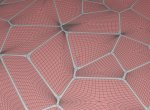
Voronoi pattern + rounded corners
- Thread starter Charless
- Start date

Hi Charles,
you need to select all polygons, then all edges.
Bevel the edges with Level one.
Switch from polygon to edge mode, now all inner fields are selected.
Call 'linear subdivide' from polygon tool menu twice, then 'Catmull-Clark subdivide' twice.
Now you have the corners rounded.
Invert the polygon selection, call 'Cover' and move up to get the geometry like in your picture.
I can make a GIF animation later if needed, but am quite busy atm.
Edit: If some points are very close, they will not work well when beveled.
Move them apart a little with point slide tool before you start.
Attachments
Last edited:
In essence:
Make your Voronoi pattern
Connect with a slightly higher value than the default to connect the nGons properly
Use point slide to get rid of too tiny corners by dragging points away from the poles.
Select all edges and call the bevel tool to make a linear bevel of factor 2 with nGons enabled
Back in Polygon mode select all nGons call inner extrude and make a tiny movement while holding shift key down to make a slightly bevel - do it again now go for the end depth.
Apply textures - you might need to add creased edges where one material assignment needs a stop.


Cheers
Frank
Make your Voronoi pattern
Connect with a slightly higher value than the default to connect the nGons properly
Use point slide to get rid of too tiny corners by dragging points away from the poles.
Select all edges and call the bevel tool to make a linear bevel of factor 2 with nGons enabled
Back in Polygon mode select all nGons call inner extrude and make a tiny movement while holding shift key down to make a slightly bevel - do it again now go for the end depth.
Apply textures - you might need to add creased edges where one material assignment needs a stop.
Cheers
Frank
Last edited:

Where do you stuck?


I think Frank's method works better than mine :smile:
I missed to explain that after making the voronoi pattern all polygons are disconnected and have to be welded together with the optimize tool.
I missed to explain that after making the voronoi pattern all polygons are disconnected and have to be welded together with the optimize tool.
The value doesn´t matter. I noticed that the default setting of 0,001 didn´t work on all places after subdividing the whole thing so I simply click the up-arrow for 1 step up. That´s all.
No secrets or mystery enclosed.
Cheers
Frank
No secrets or mystery enclosed.
Cheers
Frank


I think the script is meant to produce single polygons to make stones or shards from with shell tool.why it is so complicated?
Also it can produce very sharp geometry that is problematic for beveling.
If you need a single connected object you have to weld it with the optimize tool first, and when you try to bevel points too close you have to separate them manually first.
Also you have to switch between edge mode (beveling) and polygon mode (extruding, coloring). When looking in one mode you may miss what happens in the other :wink:
Yes. And I have a simple method to do so - but have no free hand the next hours.
You need at least a mesh or do you expect to fold a Voronoi pattern into a sculpture? Do you have one?
Cheers
Frank
Last edited:
Charless
0
Okay so I understand that Hirotos script is not (a simple) way to do it With all respect how about this?:
http://paperjs.org/examples/voronoi/
http://paperjs.org/examples/voronoi/
Charless
0
Yes. And I have a simple method to do so - but have no free hand the next hours.
You need at least a mesh or do you expect to fold a Voronoi pattern into a sculpture? Do you have one?
Cheers
Frank
Hi Frank
No need to hurry, but I want to learn and understand Voronoi, and implement it to my 3D designs > propose it to my client
something like this
https://www.youtube.com/watch?time_continue=124&v=agEvJcirfUE