You are using an out of date browser. It may not display this or other websites correctly.
You should upgrade or use an alternative browser.
You should upgrade or use an alternative browser.
hexagonal array
- Thread starter FlipFriddle
- Start date
You guys are great! I hope to have time today to go through these step by step. One unrelated question though: I notice in some of your screen shots that the Object Browser panel looks different than the version I have, 6.3.3. Most notably there is a layers tab. Am I missing an upgrade somewhere?
We´re on v7beta right now: http://www.cheetah3d.com/forum/showthread.php?t=12413Am I missing an upgrade somewhere?
Cheers
Frank
ZooHead
0
You guys are great! I hope to have time today to go through these step by step. One unrelated question though: I notice in some of your screen shots that the Object Browser panel looks different than the version I have, 6.3.3. Most notably there is a layers tab. Am I missing an upgrade somewhere?
It won't matter for this project, but I recommend going for the Beta.
Last Stage-
Attachments

Seems a lot effort to me:
:mrgreen:
Cheers
FRank
You lost me. What menu is Stamloop: Subdimo in?
")
Next Stage-
I got stuck on the mirror portion. I can't seem to select the multiple discs while in polygon mode. It looks like polygon mode is the only one that will allow the mirror command to work.
You lost me. What menu is Stamloop: Subdimo in?
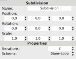
Once you have the hexagon with six polygons ready (after collapse), assign a subdivision modifier and set it to stam-loop mode.
Attachments
I can't seem to select the multiple discs while in polygon mode.
Those discs must be one single editable object for polygon selection to work on them.
If those discs are different objects, merge them first (select all objects, then call the merge command from the tool menu).
ZooHead
0
I got stuck on the mirror portion. I can't seem to select the multiple discs while in polygon mode. It looks like polygon mode is the only one that will allow the mirror command to work.
If you followed the steps it should be one object, and you're
correct you need to be in polygon mode for this to work correctly.
Try the Area Select Tool from the front view.
ZooHead
0
You lost me. What menu is Stamloop: Subdimo in?
We are throwing a lot at you all at once, but stick to it.
To make the shape as Frank illustrated first select all edges, in edge mode of course.
Then under the Selection Menu choose Toggle Crease.
This prevents the Subdivsion Modifier from rounding
the corners of the disc, the blue line are creases.
Then add a Subdivision Modifier set to Stam-Loop.
This is a brilliant way to avoid all the setup I went through.
You can now set the number of iterations till you get the number you want.
Caution: Don't work too small, when you make the disc, increase the Radius setting.
Last edited:
Here's some Bonus fun.
That's really useful. Thanks Eric
Cheers
Chris
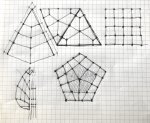
Prior to completing Steve's latest tutorial, I was trying to work out how to create a triangle out of quads. I only got as far as sketching it out on paper at the time, but I had some time to replicate it yesterday in Cheetah 3D.
This isn't the perfect description, but here goes:
1) Create a polygon object with three corners and two sections, then make editable.
2) Apply three ring cuts.
3) Collapse the centre polygon to it's centre.
4) Linear subdivide.
5) Delete a segment of polygons.
6) In point mode, create new polygons, snapping to the points that were left over from the deleted polygons.
7) Repeat Step 6 for the remaining two segments, and Optimise.
I know it's not the most efficient approach, and not as fast as Eric's approach, but I learned how to use the Collapse and Linear Subdivide tools, and the Snap and Optimise tools (thanks to Steve B's tutorial). The next thing is to follow Eric's steps and apply Array tool. Then tackle a pentagon made from quads.
Attachments

Swizl
0
Nice! My nephew was obsessed with these for a while. That and non-cube shaped Rubik's Cubes.
Ah, yes, the collapse tool!
Always forget about this one!
With this, properly sized, creasing and stam-loop triangulation the setup is very simple.
That's the problem I ran into too.
The optimum packing of spheres is based on a tetrahedron pattern.
So when we have a triangulated hexagonal shape, we need to populate it with tetrahedra via particle mesh first.
Making it a polygon object, duplicating geometry, using snapping to put the latter on the tops of the first and deleting those unwanted at the borders results in an array like this:
View attachment 30923
View attachment 30926
This would be fully symmetric with respect to the sphere packing pattern.
The original image shows something different: the spheres are packed densely in a triangular pattern horizontally,
but vertically tha packing follows a less dense squared pattern, which allows a hexagonal shape at the top.
This is more accurate to what I was trying to create, but your technique is really beyond me at this point. I'll noodle with it some though and keep you all posted. Sorry, I've been out of this for a bit; some more pressing projects at work pushed this illustration to the back burner. Now I'm ready to finish it. Expect more questions.
2nd part of the diagram
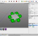
Here's the second element of the diagram I am struggling with too (I still haven't resolved the large structure I started the thread with). I've trying to create a diagram of a molecule of 6 atoms connected by cylinders that represent the bonds. I made a disc to create a hexagon and the a particle mesh to get spheres at each point. Then I created another particle mesh to create the 6 bonds, but as you can see, even with the mesh set to edges, the cylinders only line up on two of the edges of the hexagonal disc. They seem to have some rotation setting that is overriding the edge command. I want all of the cylinders to ring the disc so it looks like the "bond" cylinders are each connected to two atoms in a ring. Any thoughts?
You guys are all a big help BTW. Thanks.